
Lift System with Tilt Function
Launching a heavy tender from a large platform is a controlled operation — or it should be. When the platform reaches water level and the tender meets the surface at an angle, the transition from platform to water becomes a force management problem. Without a tilt function, that moment relies on crew coordination, manual adjustments, and timing. Repeated over a season, it is slow, physically demanding, and a source of unnecessary wear on both the tender and the people handling it.
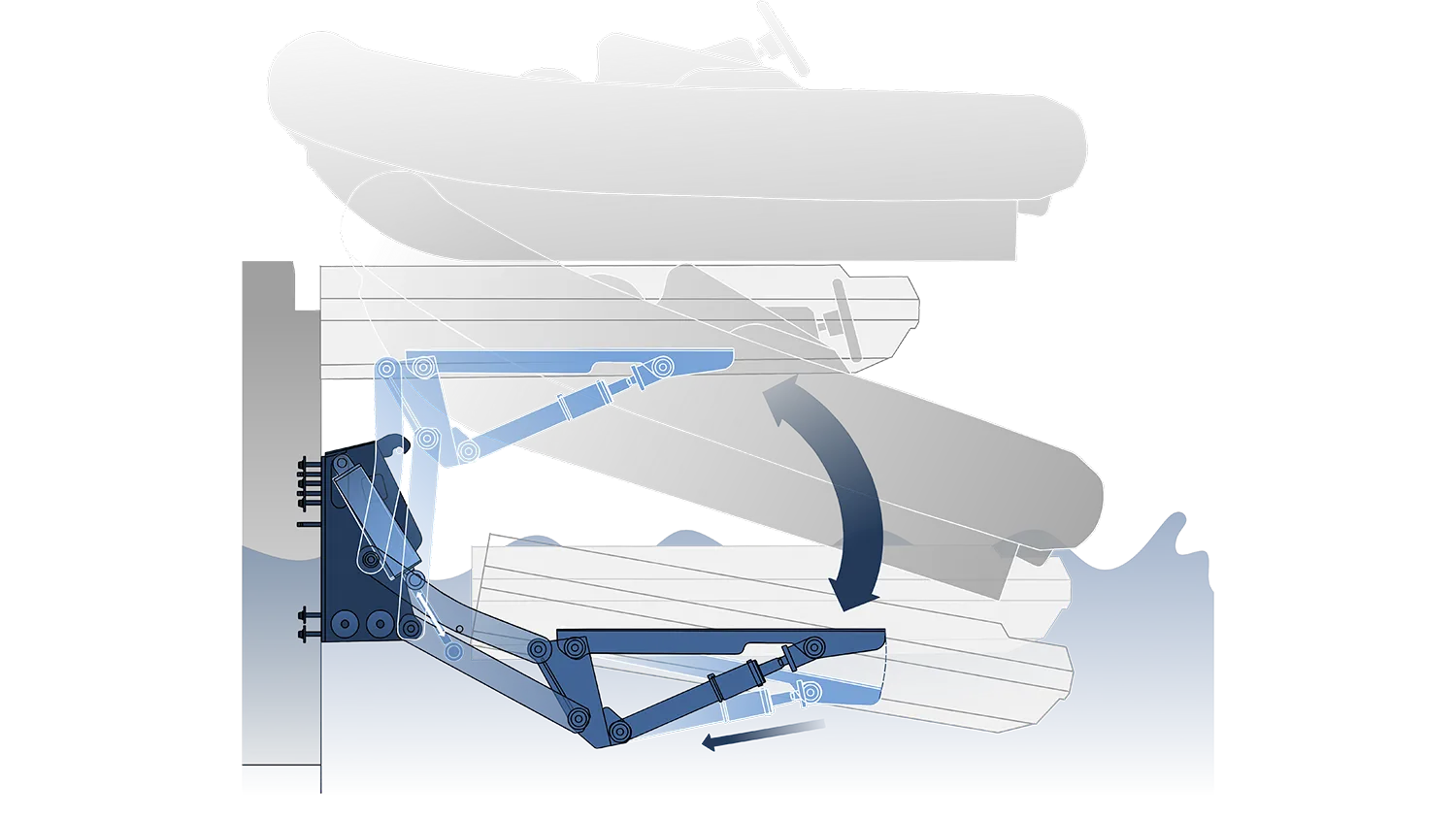
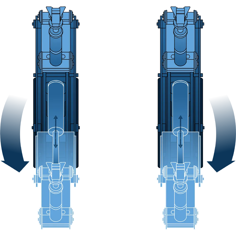
The Lift System with Tilt Function eliminates this. An additional hydraulic tilt cylinder in the platform carrier tilts the carrier downward as the platform descends — angling the platform so the tender meets the water bow-first and slides off in a single, controlled motion. No repositioning. No manual intervention. The same sequence in reverse brings the tender smoothly back onto the platform.
One additional cylinder — fundamentally different launch behaviour
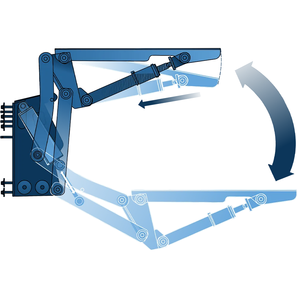
The tilt function adds a single hydraulic cylinder to the platform carrier. When retracted, this tilt cylinder pivots the platform carrier downward, inclining the platform toward the water at the precise angle required for the tender to transition from platform to water without lifting, wedging, or requiring manual guidance at the bow.
The tilt angle and travel range are not fixed — they are defined during the engineering phase based on the specific platform dimensions and the weight of the tender. A larger, heavier platform carrying a 500 kg tender requires a different tilt profile than a compact system with a 200 kg RIB. H+B technics engineers the tilt cylinder stroke and mounting geometry to the actual load parameters, not a generic specification.
The critical advantage of a hydraulic tilt cylinder over mechanical or passive solutions is controllability: the angle can be held at any intermediate position, adjusted within the operating range, and reversed in a controlled sequence — without relying on gravity, springs, or manual unlocking mechanisms.
Controlled entry — the tender reaches the water without manual correction
The critical moment in tender handling is not the lowering — it is the transition at the waterline. When a platform descends level, the tender's bow and stern reach the water simultaneously. The buoyancy forces that immediately act on the hull are distributed unevenly, particularly on RIBs and tenders with pronounced rocker. Crew standing at the stern must lift or guide the bow. In a sea state, this becomes difficult.
With the tilt function active, the platform is already angled before the tender contacts the water. The bow enters first. Buoyancy acts progressively along the hull from bow to stern, allowing the tender to float free without lateral force from the platform. The crew releases the tender from the stern — one movement, from one position — and the tender is in the water.
In retrieval, the sequence reverses: the platform is tilted as the tender is brought alongside, guiding the hull onto the platform bow-first. Once the tender is seated, the tilt cylinder extends to level the platform, and the lift raises it to the stowed position. The entire cycle requires fewer crew, less physical effort, and less time.
No retrofit complexity — delivered ready to connect
The tilt function is not an aftermarket addition fitted to an existing lift system. It is engineered as an integral part of the platform carrier from the outset. The tilt cylinder mounting points, pivot geometry, and hydraulic connections are designed into the carrier structure — not bolted on externally. The platform carrier with tilt function has the same structural integrity as a standard carrier, with no local stress concentrations at add-on attachment points.
The complete system is delivered fully pre-assembled and function-tested from H+B technics in Münster. The tilt cylinder is connected, the hydraulic circuit is pre-plumbed, and the operating range is pre-configured for the specified platform and tender weight. On-board installation connects the hydraulic lines to the vessel's system — no additional workshop preparation is required at the installation site.
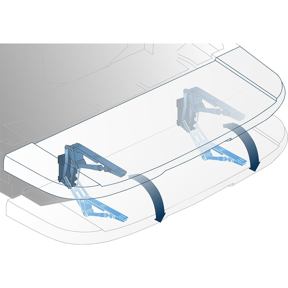
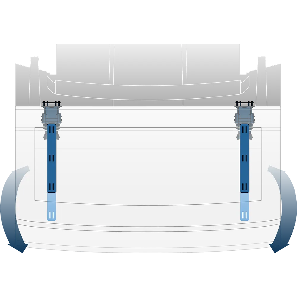
Visual overview
Explore how the tilt function integrates into the lift system — the platform carrier tilting downward, the tender being guided into the water, and the full system from every angle.

Technical Specifications
The Lift System with Tilt Function extends the standard H+B technics lift system with an integrated hydraulic tilt cylinder in the platform carrier. The tilt cylinder retracts to incline the platform, enabling controlled, bow-first launching and retrieval without manual adjustment. All components are pre-assembled and function-tested.
TILT MECHANISM
Hydraulic tilt cylinder integrated in the platform carrier. Retracts to tilt the carrier downward, extending to return the platform to level position. Cylinder stroke and mounting geometry defined per project based on platform dimensions and tender weight.

TILT ANGLE
Variable, defined during engineering phase. Tilt range optimised for the specific platform size and tender mass to ensure controlled bow-first water entry without excessive angle.
INTEGRATION
Tilt cylinder designed as an integral component of the platform carrier — not an external retrofit addition. Mounting points and pivot geometry engineered into the carrier structure for uniform load distribution.
MATERIAL
Electropolished AISI 316L stainless steel throughout. All structural components, cylinder housings, and mounting hardware manufactured from the same alloy for consistent corrosion resistance.
HYDRAULIC CONNECTION
Pre-plumbed hydraulic circuit at delivery. Connects to the vessel's on-board hydraulic system. Operating pressure and flow requirements confirmed during engineering phase.
"The lifts are not just functional — they match our design and standards. With H+B, it feels more like a team than a supplier relationship."

Frequently asked questions
Answers to the most common questions about the Lift System with Tilt Function.
The tilt cylinder is mounted in the platform carrier between the carrier frame and the platform mounting surface. When the cylinder retracts, it shortens the distance between two pivot points, rotating the platform surface downward around the forward pivot axis. The degree of rotation — the tilt angle — is determined by the cylinder stroke and the geometry of the pivot points, both defined during the engineering phase for the specific platform.
The tilt is a separate hydraulic circuit within the integrated system — it can be operated independently of the lift movement or sequenced with it, depending on the vessel's control system configuration. In a typical launch sequence: the lift lowers the platform to water level, the tilt activates to angle the platform, and the tender floats free. In retrieval, the sequence reverses. The specific sequencing is defined during installation.
There is no fixed upper limit — the system is engineered individually for each project. The tilt cylinder stroke, pivot geometry, and carrier structure are specified based on the platform dimensions and the expected tender weight. H+B technics has engineered tilt systems for tender weights ranging from compact RIBs to large, heavy tenders on superyacht platforms.
In most cases, yes — provided the existing platform carrier has sufficient structural depth and the geometry allows the tilt cylinder to be integrated at the correct pivot point. H+B technics assesses retrofit feasibility based on drawings of the existing installation. Where the carrier structure is compatible, the tilt cylinder and hydraulic circuit can be added without replacing the full system.
Lead time depends on the engineering complexity of the specific installation and the current production schedule. Typical projects run 6–10 weeks from confirmed order to delivery. Because the tilt geometry is defined for each platform individually, lead time is calculated after the engineering phase and drawing confirmation. The system is delivered fully pre-assembled and function-tested.
Need more help?
Our team is ready to answer your questions
Customization option
Tailored solutions perfectly suited to your needs. At H+B technics, we not only offer our proven products but also the opportunity to customize them according to your specific requirements. Our experienced team is ready to support you in developing and realizing bespoke products for your yacht or project, always with a strong focus on quality, innovation, and precision.
Whether it’s special dimensions, functions, or an entirely new design, we bring your vision to life. Rely on our expertise and let’s make your ideas a reality together.
Julian Arnsmann
Head of Project & Engineering


Start your project
Every Lift System with Tilt Function is individually configured for your vessel and platform dimensions. Share your platform drawings and tender specifications, and we support you from the first concept to the finished installation.

